
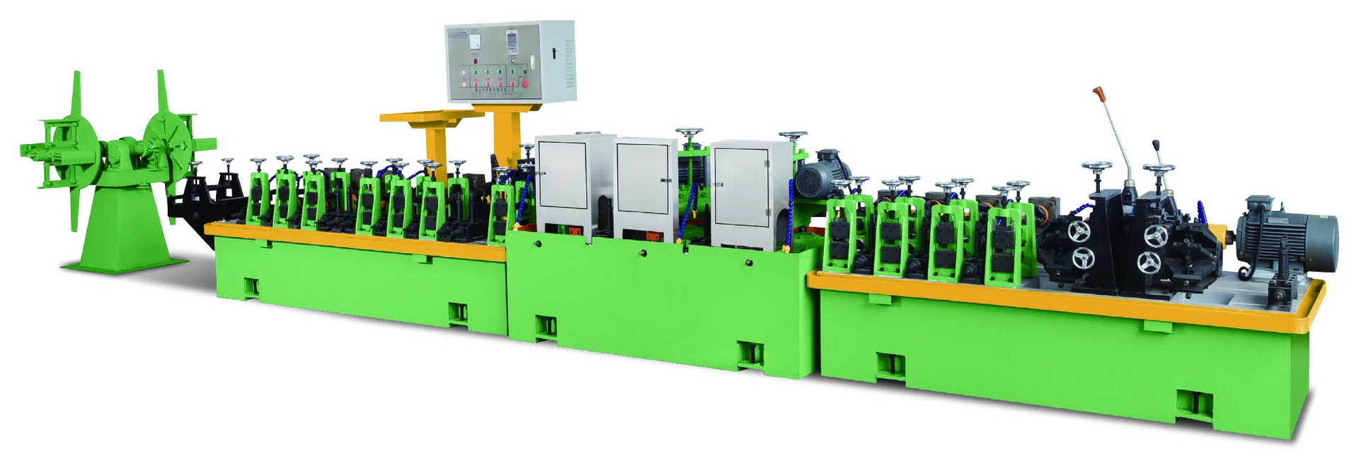
A welded tube mill starts with metal strip and produces welded tube through a continuous production line. The first selection decision is the tube range the factory must make. Model names alone do not identify the right line because each model covers a different outside-diameter range, wall-thickness range and listed machine footprint.
This guide uses the current MAXDO Standard Tube Mill records to show a practical first screen. The catalog confirms seven models and describes the offer as a complete welded-tube production line. It does not publish a model-by-model list of included line units, production rate, material suitability or utility requirements, so those items are kept outside the numerical comparison.
Tube diameter and wall-thickness range
Write the regular tube range before looking at the largest model. Record the smallest and largest outside diameter, the regular wall-thickness range, the tube shape and the expected future range. If the line will make several sizes, use the full range that must be covered rather than one representative size.
The current model table is:
| Model | Tube outside diameter | Wall thickness | Listed machine dimensions |
|---|---|---|---|
| MD-40S | φ6–32 mm | 0.2–1.0 mm | 20 m × 1.0 m |
| MD-40 | φ8–51 mm | 0.3–1.8 mm | 21.5 m × 1.1 m |
| MD-40L | φ12–64 mm | 0.3–2.0 mm | 21.5 m × 1.1 m |
| MD-50 | φ25–76 mm | 0.3–2.0 mm | 24 m × 1.2 m |
| MD-60 | φ50–114 mm | 0.3–2.5 mm | 26 m × 1.4 m |
| MD-80 | φ89–186 mm | 0.8–3.5 mm | 32 m × 2.3 m |
| MD-100 | φ114–219 mm | 1.0–5.0 mm | 36 m × 3.5 m |
These ranges are screening data. A listed range does not by itself prove that every material, weld condition or production requirement will run successfully at every point in the range.
Wall thickness with tube diameter
Diameter is only one fit condition. A tube can fall inside a model’s diameter range and still fall outside its listed wall-thickness range. Screen both values together.
For example, suppose the regular requirement is 60 mm outside diameter and 2.0 mm wall thickness:
| Candidate | Diameter check | Wall check | Listed footprint | Initial result |
|---|---|---|---|---|
| MD-40L | 12–64 mm includes 60 mm | 0.3–2.0 mm includes 2.0 mm | 21.5 m × 1.1 m | Fits the listed range |
| MD-50 | 25–76 mm includes 60 mm | 0.3–2.0 mm includes 2.0 mm | 24 m × 1.2 m | Fits the listed range |
| MD-60 | 50–114 mm includes 60 mm | 0.3–2.5 mm includes 2.0 mm | 26 m × 1.4 m | Fits the listed range |
All three models pass this first numerical screen. The smaller listed footprint makes MD-40L the first model to discuss when 60 mm is the regular upper size, while MD-50 or MD-60 may be more appropriate when a confirmed future range requires the additional diameter or wall-thickness coverage. The table narrows the discussion; it does not select a final configuration by itself.
Machine dimensions and factory space
The dimensions in the table describe the listed machine dimensions. They are useful for comparing scale, but they are not a complete foundation or installation drawing. A factory review must also account for strip loading, finished-tube removal, operator access, maintenance access and any equipment included in the confirmed line arrangement.
A simple footprint calculation shows why the model choice affects the building discussion:
- MD-40L nominal rectangle: 21.5 m × 1.1 m = 23.65 m².
- MD-50 nominal rectangle: 24 m × 1.2 m = 28.80 m².
- MD-60 nominal rectangle: 26 m × 1.4 m = 36.40 m².
These are arithmetic comparisons of the listed rectangles, not usable-floor-area promises. Do not use them as a substitute for a final layout drawing.
Units in the complete tube mill line
MAXDO describes the Standard Tube Mill family as complete welded-tube production lines. The current local records do not establish the exact production units included with each MD model. A technical request should therefore identify the model candidate and ask for the confirmed line arrangement for that model.
The request should include:
- Regular and future tube outside diameters.
- Regular and future wall thicknesses.
- Tube shape and material information.
- Expected production context and output requirement.
- Available floor length and width.
- Strip loading and finished-tube handling direction.
- Any drawing, sample or existing line information that affects the assessment.
This information lets the technical discussion connect the model table to the actual factory instead of treating the model name as a complete specification.
Tube mill model screening procedure
Use this sequence for each new tube size plan:
- Write the regular minimum and maximum outside diameters.
- Write the regular minimum and maximum wall thicknesses.
- Remove every model whose listed range misses either boundary.
- Compare the remaining footprints with the available building space.
- Test confirmed future sizes against the same two range limits.
- Request the selected model’s included units and final line arrangement.
- Confirm the material and production conditions through technical review.
The process prevents a common mistake: choosing the largest model because it appears safest without checking whether its footprint and configuration match the factory.
What the tube mill table confirms
The published table can establish the listed model names, tube ranges, wall-thickness ranges and machine dimensions. It cannot establish a universal material range, production rate, weld quality, changeover time, utility requirement or the exact equipment included in each line. Those points must be handled as project-specific technical questions rather than filled with assumptions.
Choose the tube mill from range, thickness and footprint
Select a welded tube mill from the complete range the factory must produce. Check outside diameter and wall thickness together, compare the listed footprint, then request the confirmed line arrangement for the model that passes the screen. For the 60 mm by 2.0 mm example, MD-40L, MD-50 and MD-60 all pass the listed range check, but their future coverage and building footprints lead to different technical discussions.