
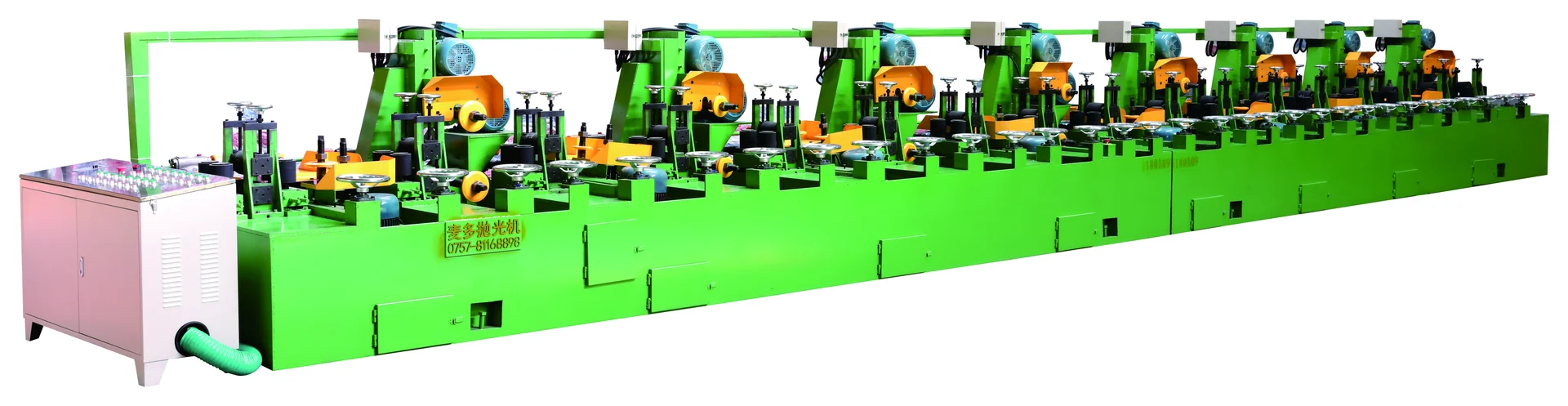
A machine range should cover the work the factory expects to run, including confirmed future requirements, while still fitting the building and the actual process. Choosing only the largest listed range can create unnecessary footprint and configuration questions. Choosing only today’s smallest size can exclude work the factory already plans to add.
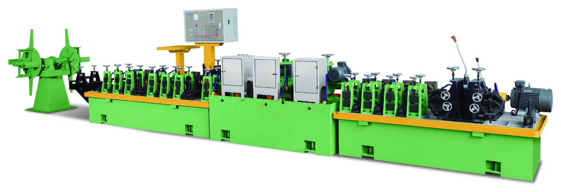
MAXDO welded-tube production line shown in the local product image.
Use the regular range as the starting point, test future sizes against the same fields and then compare the physical machine envelope.
Current and future tube sizes
Create one table before selecting a model:
| Requirement | Current project | Future or occasional project | Decision use |
|---|---|---|---|
| Workpiece shape | Round, square or pipe | Additional shape if planned | Select the process family |
| Diameter or section | Regular minimum and maximum | Future minimum and maximum | Test model range |
| Wall thickness | Regular range | Future range | Test family specification |
| Length | Typical and maximum | Future length | Check handling or polishing length |
| Surface or output | Outside, inside or finished tube | Additional requirement | Select the process path |
| Factory space | Available footprint | Expansion possibility | Check listed dimensions |
The future column should contain a real planned requirement or an explicit scenario. It should not be filled with an arbitrary maximum just because a larger model exists.
Standard Tube Mill range example
Assume the factory currently makes 25–60 mm tube with 0.8–2.0 mm wall thickness and expects to add 76 mm tube later.
| Model | Listed diameter | Listed wall thickness | Nominal footprint area |
|---|---|---|---|
| MD-40L | 12–64 mm | 0.3–2.0 mm | 21.5 × 1.1 = 23.65 m² |
| MD-50 | 25–76 mm | 0.3–2.0 mm | 24 × 1.2 = 28.80 m² |
| MD-60 | 50–114 mm | 0.3–2.5 mm | 26 × 1.4 = 36.40 m² |
MD-40L covers the regular range but misses the planned 76 mm size. MD-50 covers both the current and future diameter range while matching the stated wall-thickness range. MD-60 also covers the future size but starts at 50 mm, so it does not cover the current lower range of 25 mm.
The nominal footprint calculation is a comparison of the listed rectangle. It does not include clearance, handling, utilities, foundation or unlisted auxiliary equipment.
Round-tube and industrial-pipe polishing ranges
For round-tube polishing, compare the regular and future diameter with the MA/ME ranges of 12–63 mm and 51–129 mm. For industrial pipe polishing, compare the range with the MG records from 6–51 mm through 114–426 mm and the listed 1.5–10 mm wall thickness.
For internal polishing, add polishing length and generation to the range test. A repeated model number must stay attached to its generation. For square tube, use width, height, wall thickness, polished faces and handling information because the current public data does not contain a complete model table.
Range, wall thickness and machine footprint
A wider range can change:
- listed machine length and width;
- pipe or tube support requirements;
- loading and removal paths;
- operator and maintenance access;
- electrical or configuration questions;
- the amount of building space committed to one process.
The current data does not publish a universal changeover time, output rate or capacity relationship between models. Do not describe a larger model as faster or more flexible unless the project source confirms that claim.
Required size range screening
- Write the regular minimum and maximum size.
- Write the planned future minimum and maximum size.
- Record wall thickness, length and processing surface.
- Remove models that miss any required boundary.
- Compare nominal dimensions with the available factory path.
- Check the configuration and support questions for the remaining candidates.
- Send the complete range table with the inquiry.
Choose the range from current and future sizes
Choose a machine range from the work the factory actually needs, then test confirmed future sizes against diameter, wall thickness, length, surface and footprint. In the example, MD-50 covers the current 25–60 mm range and the planned 76 mm size while MD-40L does not. That is a defensible first screen; the final model still requires configuration and factory review.