
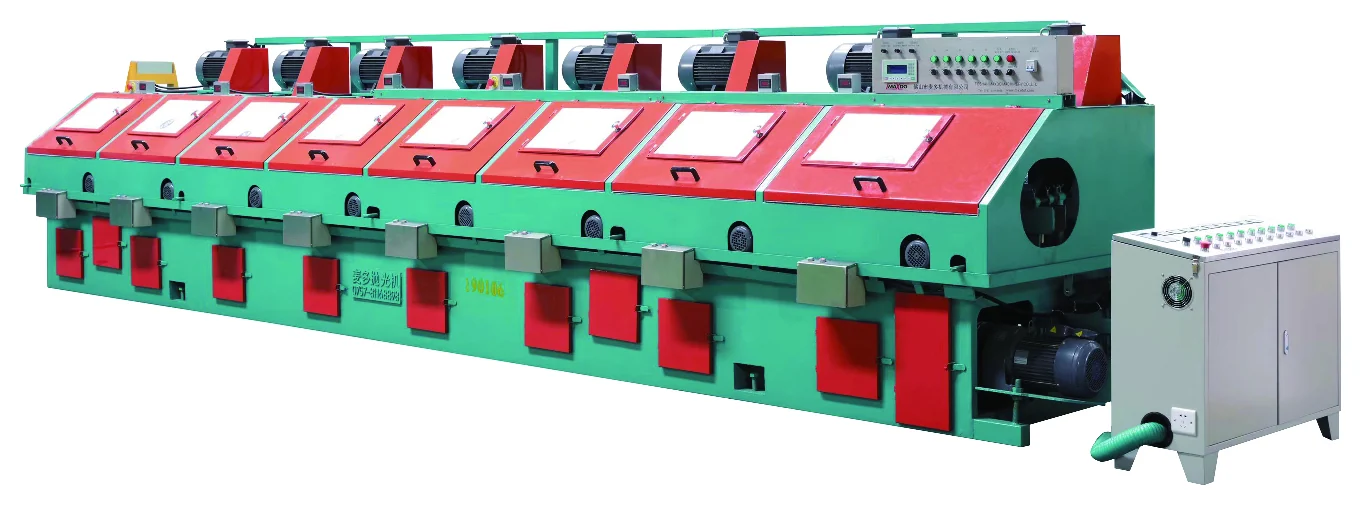
A specification table is useful only when each field is read inside the correct process. “Diameter,” “power,” “stations” and “machine dimensions” do not answer the same question across a welded-tube line, an external polishing machine and an internal polishing machine.
The safest method is to read the process label first, then the range, then the configuration fields and finally the factory footprint. This article applies that method to the current MAXDO tables.
Equipment process and product family
The current records describe separate equipment paths:
| Process | First fields to read |
|---|---|
| Welded-tube production | Tube outside diameter and wall thickness |
| Round-tube outside polishing | Tube diameter, wall thickness and support |
| Industrial round-pipe outside polishing | Pipe diameter, wall thickness and support |
| Internal pipe polishing | Generation, model, diameter range and polishing length |
| Square-tube polishing | Width, height, wall thickness and polished faces |
A number should never be copied from one path into another. Start by identifying the product family and the operation the machine performs.
Standard Tube Mill specifications
The Standard Tube Mill table contains model, horizontal shaft, vertical shaft, tube outside diameter, wall thickness, drive motor and machine dimensions. Diameter and wall thickness are the first fit fields.
For example, the table lists:
| Model | Tube outside diameter | Wall thickness | Drive motor | Listed dimensions |
|---|---|---|---|---|
| MD-40L | φ12–64 mm | 0.3–2.0 mm | 11 kW | 21.5 m × 1.1 m |
| MD-50 | φ25–76 mm | 0.3–2.0 mm | 11 kW | 24 m × 1.2 m |
| MD-60 | φ50–114 mm | 0.3–2.5 mm | 15 kW | 26 m × 1.4 m |
If the regular requirement is 60 mm outside diameter and 2.0 mm wall thickness, all three rows pass the listed range screen. The next decision is future size, nominal footprint and the confirmed line arrangement. Drive motor power is a listed field; it is not a direct production-rate or finish guarantee.
MA and ME round-tube specifications
The round-tube tables use diameter range, polishing motors, wall thickness, main motor, total power, tube support and machine dimensions. The ME table also lists adjustment motors.
| Model | Tube diameter range | Wall thickness | Adjustment motors | Tube support |
|---|---|---|---|---|
| MA-8 | 12–63 mm | 0.3–2.5 mm | Not listed in the MA table | Bakelite plate |
| MA-8L | 51–129 mm | 0.3–2.5 mm | Not listed in the MA table | Rubber roller |
| ME-8M | 12–63 mm | 0.3–2.5 mm | 0.12 kW × 8 | Bakelite plate |
| ME-8L | 51–129 mm | 0.3–2.5 mm | 0.12 kW × 8 | Rubber roller |
For a 55 mm tube with a 1.2 mm wall, MA-8 and ME-8M pass the listed size screen. The adjustment-motor field explains why ME-8M belongs in the comparison. It does not prove a universal advantage without a project requirement that uses that adjustment equipment.
MG industrial-pipe specifications
MG records use pipe diameter, polishing motors, wall thickness, main motor, total power, tube support and machine dimensions. The listed wall-thickness range is 1.5–10 mm, which is a different screening context from the 0.3–2.5 mm MA and ME range.
A 100 mm pipe with a 5 mm wall falls within MG-114 at 15–114 mm and also within MG-219 at 50–219 mm. Compare the regular and future range, the listed power and the handling arrangement before discussing the candidate. A wider range is not automatically a better fit.
Internal polishing specifications by generation
Internal polishing records add generation and polishing length to the comparison. The same model number appears in several generations, so the generation must remain attached to the model.
| Candidate | Listed diameter range | Polishing length | Stations | Spindle speed |
|---|---|---|---|---|
| Second-generation MD133 | φ50–φ133 | 1.5–6.1 m | 3 | 3000 r/min |
| Third-generation MD133 | φ63–φ133 | 1–6.1 m | 3 | 6000 r/min |
| Fifth-generation MD133 | φ63–φ133 | 4–6.1 m | 3 | 6000 r/min |
For a 4.5 m polishing length, all three listed rows include the example length. The second-generation row starts at 1.5 m, the third-generation row at 1 m and the fifth-generation row at 4 m. The difference helps define the technical question; it does not establish a universal ranking between generations.
Machine dimensions and capacity fields
- Machine dimensions describe the listed equipment envelope. They do not prove the required building clearance or material path.
- Total power describes a listed electrical value. It does not by itself establish output or finish quality.
- Polishing motor count describes the listed machine arrangement. It does not replace a surface-result discussion.
- Stations describe the listed internal-polishing arrangement. They do not automatically define the final result.
- Wall thickness is a fit field, but material and process condition still matter.
The current public data does not define a universal material range, production rate, roughness measurement or maintenance schedule for all families. Read the table for what it actually records.
Project fit comparison fields
A useful internal comparison keeps only fields that affect the current decision:
| Project question | Catalog fields to compare |
|---|---|
| Does the machine cover the workpiece? | Diameter, section, wall thickness and length |
| Which surface does it process? | Product family and process description |
| Which model needs discussion? | Generation, model and range |
| Can the factory receive it? | Machine dimensions and handling path |
| What must the inquiry explain? | Material, finish, configuration and acceptance method |
Reading process, fit and model fields
- Identify the process and product family.
- Check the diameter or section range.
- Check wall thickness and length.
- Compare configuration fields within the same family.
- Check the listed dimensions against the factory path.
This order keeps a convenient number, such as motor power, from becoming the first and only selection criterion.
Read process and fit fields together
Read the process before the number. Use diameter and wall thickness to screen tube and external-polishing models, keep generation attached to internal-polishing model numbers, and use stations, motors and dimensions to deepen the comparison. The current MAXDO tables support a disciplined first screen; the final discussion still depends on the actual material, surface, configuration and factory conditions.